My Rust Diary
May 12, 2008; engine compartment "longs" and suspension consoles;
Sorry, but I haven't done an entry for a while. I've been making good progress.
Putting the outer suspension console back on.
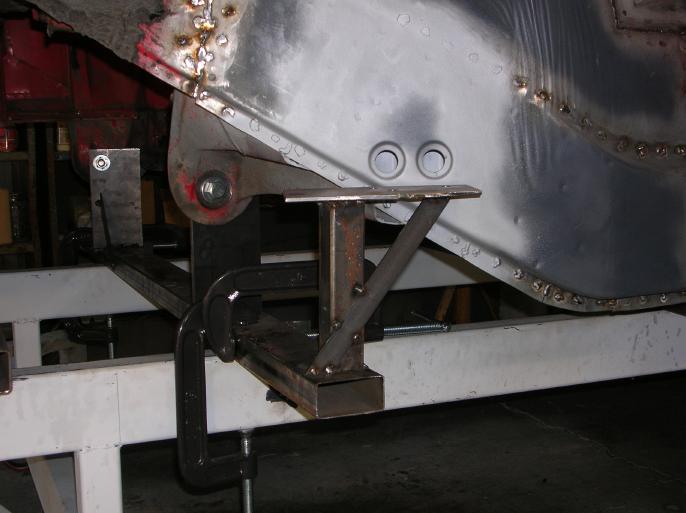
In the following photo, I've put the suspension jig in place;

Here it is with the console just held in place by the jig; There are three bolts going through the jig and into the console, which can't be seen.
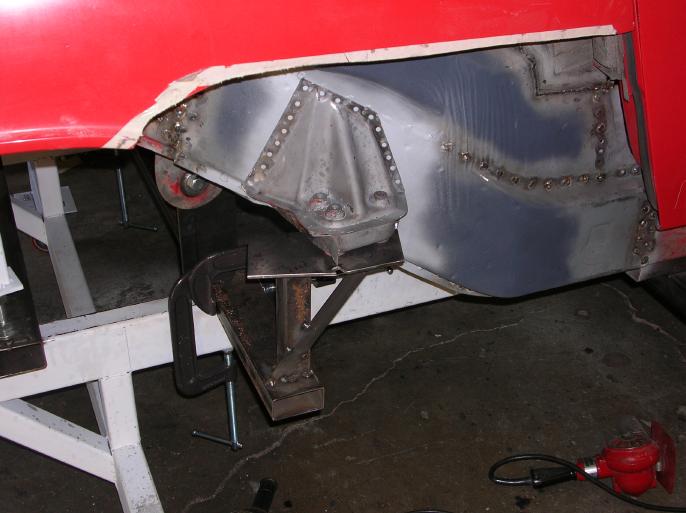
and here it is with a couple welds thrown on.

I welded a cross-bar spanning the seat area and cut out the lower section of the firewall bulkhead. (it's currently trimmed back a lot more, but this photo shows the added temporary support)
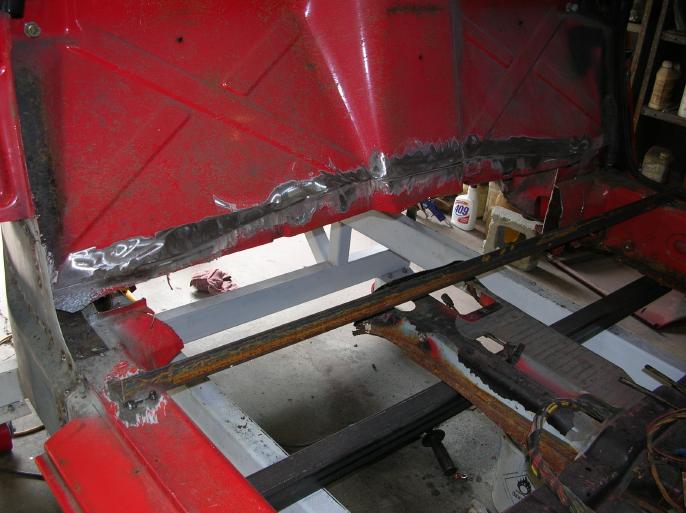
That dark square tube is one of the body supports. Although it looks like the center-console is resting on the tube, it's actually floating in space!!
I removed the inner suspension console;
Due to needing to reinforce (replace a section) of the inner surface of the longitudinal, I had to remove the inner suspension console. Due to wanting to save money, I planned on re-using the console, and that meant that I'd have to locate and drill out a whole bunch of spot welds. Some of the spot welds are hidden by the welding done by the factory when they add the two pieces that span from inner to outer console (normal welds are covering some of the spot welds).
This takes a lot of time and I'd highly recommend that you just buy a new console from Restoration Designs.
One of the reasons I'm posting up these photos is so you can get an idea of where the welds are. You should be able to have your browser view the photos "full screen" if you want.
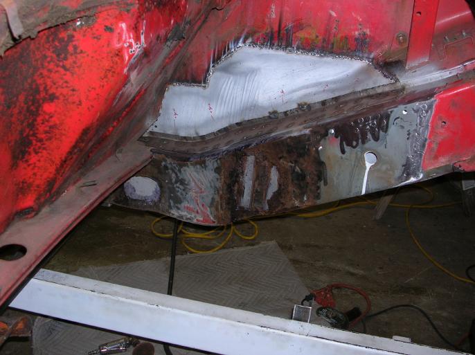
Replacing the steel that was behind the motor mount bracket.
I cut out the outer skin of the longitudinal that was behind the motor mount and also a section that was along the bottom. I then tack welded the what was left of the outer skin to the inner skin. (those are the welds around the perimeter)
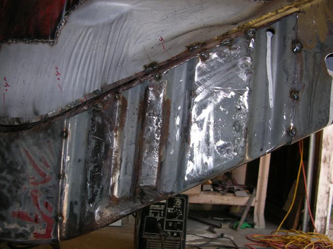
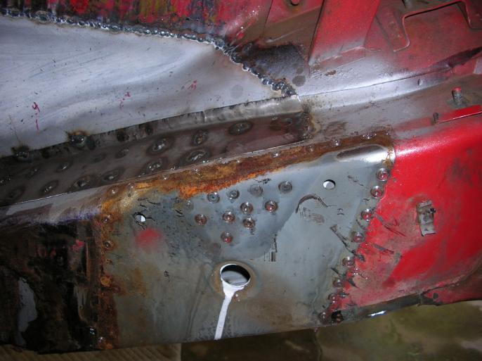
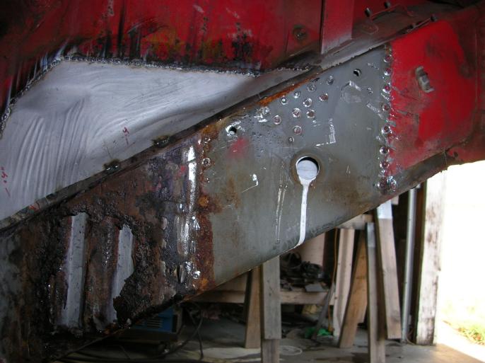
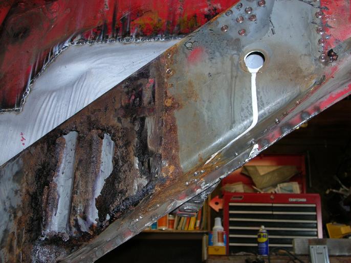
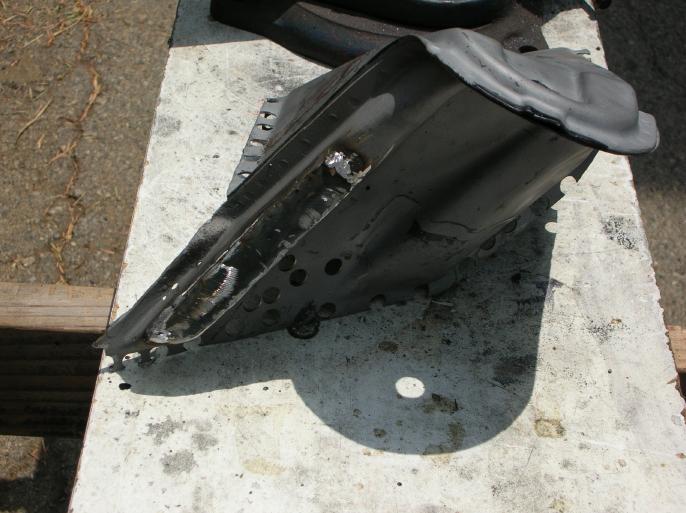
I then made up this replacement section. (I didn't have to make up that "pocket" on the bottom edge due to the fact that I'm not going to use "4 cylinder" type motor mount brackets)
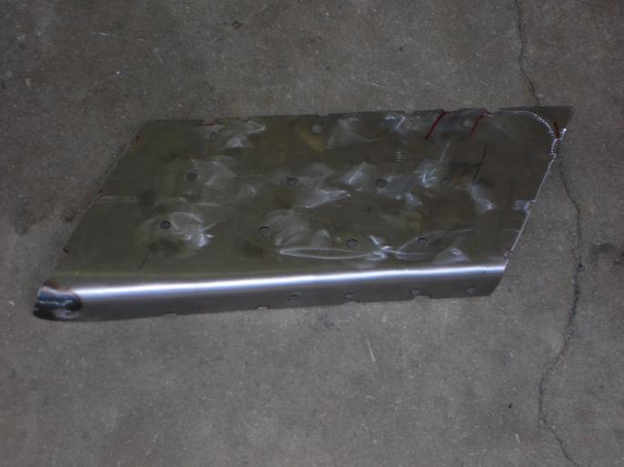
The notches along the perimeter are to clear the "tack" welds. The placement of the holes is critical so that they hit the high points of the inner steel.
The next two photos show the plate held in place and also welded in.

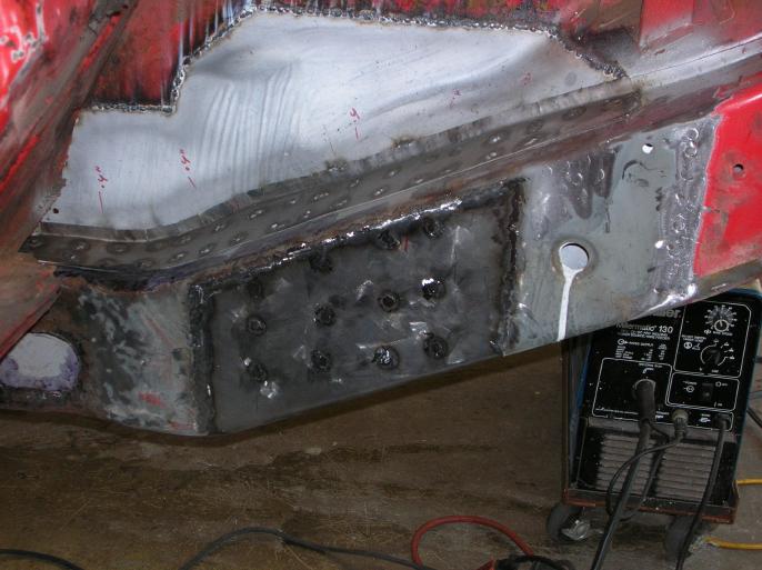
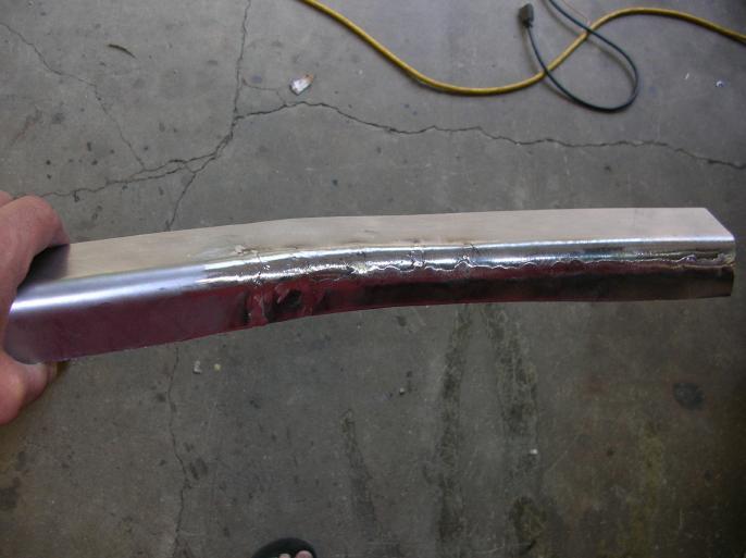
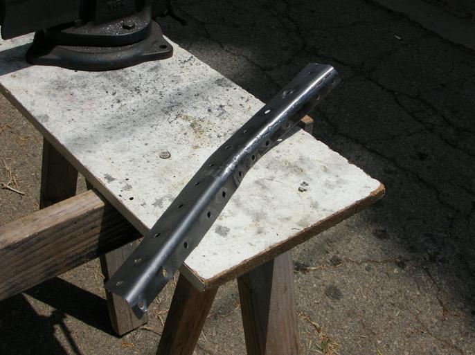
Now you may ask; "gee Wes, what kind of special tool did you use to get that bend".
It's no big buck thing! Just a section of 3/4" round stock welded to some thick steel plate. I had it sitting around from some project I can't even remember. I had to weld that second plate on the side to make it flush with the round stock.
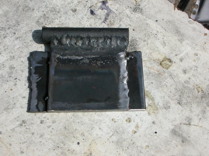

It's just that, a vice, and a BFH.
Building the cover plate that goes on the upper / inside edge;
The next two photos show the cover plate I made for the upper / inside edge of the longitudinal. It's not as easy as it looks due to the inside surface not being "flat".
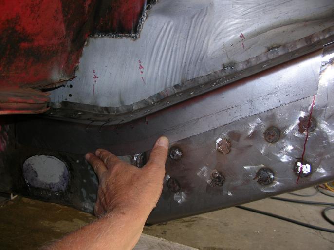
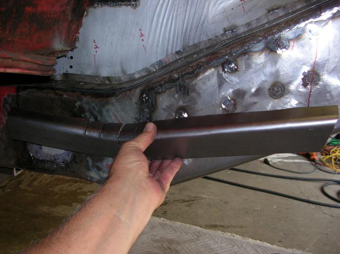
It's done by making an I-board template on the side of the longitudinal. The transferring that to a sheet of 18 gauge plate. Then marking cut lines 3 inches off of that line.
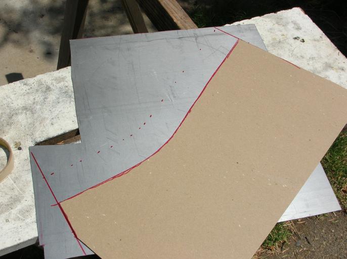
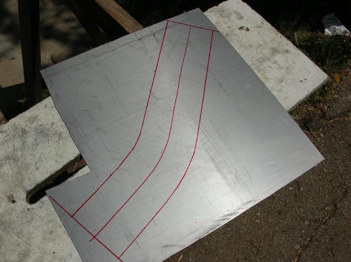
Cuts were made in it due to the shape of the inside surface.
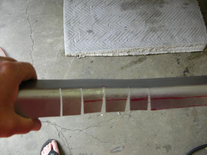
Then, due to my not liking the size of the opening between sections, I cut it along the marked red line and made up a piece to fill it in.
Here is the finished cover plate.
Working on the inner suspension console;
There were areas on the bottom edge of the inner suspension console that had rusted through.
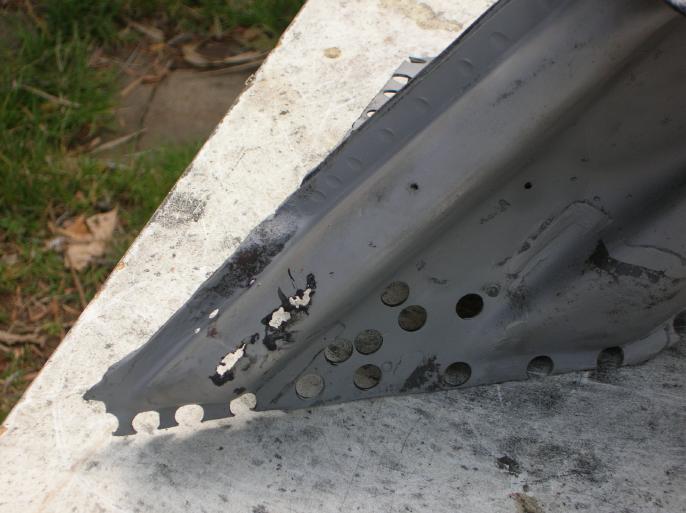
I cut out the rusted area and made a replacement piece. then I welded it in place.
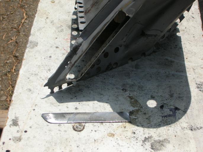
Welding the inside stuff back on;
I got out the suspension jig again and used it to position the inner suspension console.
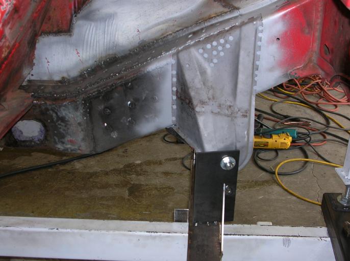
Then I welded in the console and also the cover plate for the inside upper edge.
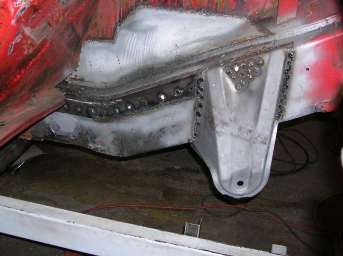
That's it for now.
go to the next "rust diary" page
go to the prior "rust diary" page
return to my "rust diary" entry page
return to my site's entry page
Wes Vann