My Rust Diary
April 3, 2008; engine compartment "longs";
After building up the work platform, I got back to figuring out how I wanted to address the rust.
Covered under this date is a fair amount of time.
Once again, I've got to say a couple things. I'm not a professional body man. How bad your rust problem is will dictate what has to be done. Things like converting to a water cooled engine will make a difference in what you can do.
You can't weld to rust! If it's not shiny metal, you can't weld to it! This includes the coatings of rust converters like Por15! (the only exclusions are "weld-through" primers like 3M Weld-Thru 2) Don't try to bend this rule. I've tried! I'm not going to go into how I know this, due to it making me look like an idiot)
If you are doing anything other than a single section, you have to know the "sequence" that Karmann put the bodies together. In other words, you have to remove items and replace them in the same order that they were originally done. What complicates this is that the bodies were put together as partial assemblies. If you look at the factory manual and also at the "PET" parts diagrams, you will notice that individual metal body pieces were never sold separately. They were assemblies of several pieces.
Some of the photos are out of sequence.
What I'm doing at this date is exploring how bad the rust is in the longitudinal that is below the battery tray. Best known to 914 owners as the "hell hole" section. I also knew at this point that I was going to have to replace the inner fender panel, which is part of that longitudinal. Auto Atlanta sells a replacement panel and that's where I got it (it's two pieces of stamped metal, welded together).
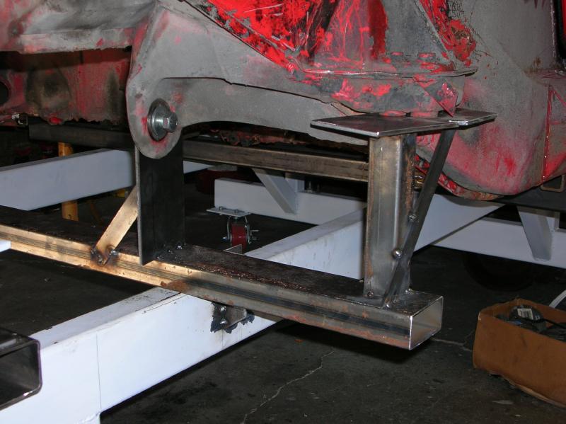
Prior to removing the inner fender panel, I made up a jig for the suspension points (covered in the "platform diary"). This photo shows it, after a section of the outer fender was removed.

I then cut out a section of the inner fender / longitudinal.
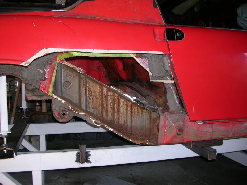
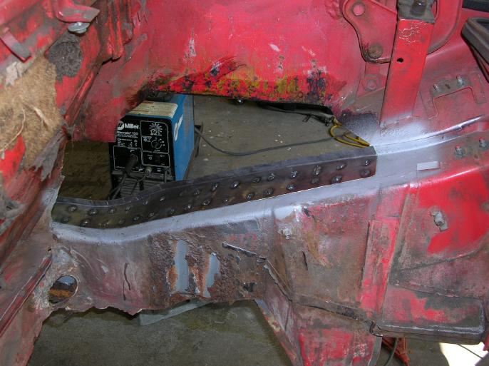
At this point it's good to point out a couple things and it's best to start with a photo taken from within the engine compartment.
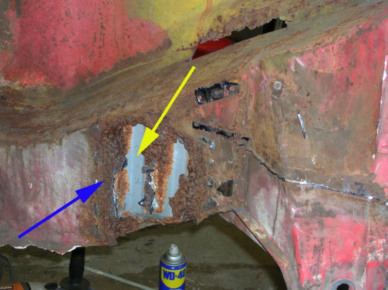
If you remove the engine mount from a four cylinder 914, you would find a smooth surface on the longitudinal. At least if it hadn't rusted out as mine did.
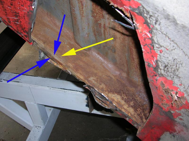
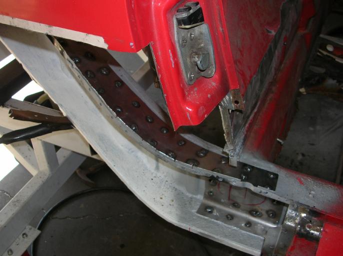
The side surface is constructed of two metal stampings!
The outer is smooth and goes all the way to the pinch weld to the outer fender section. That's what the blue arrow is pointing at.
Within that is the corrugated metal stamping, which the yellow arrow is pointing at.
On my car, the outer section is rotted and needs to be addressed. The inner corrugated section is in reasonable condition.
The next two photos show the inside of the longitudinal;
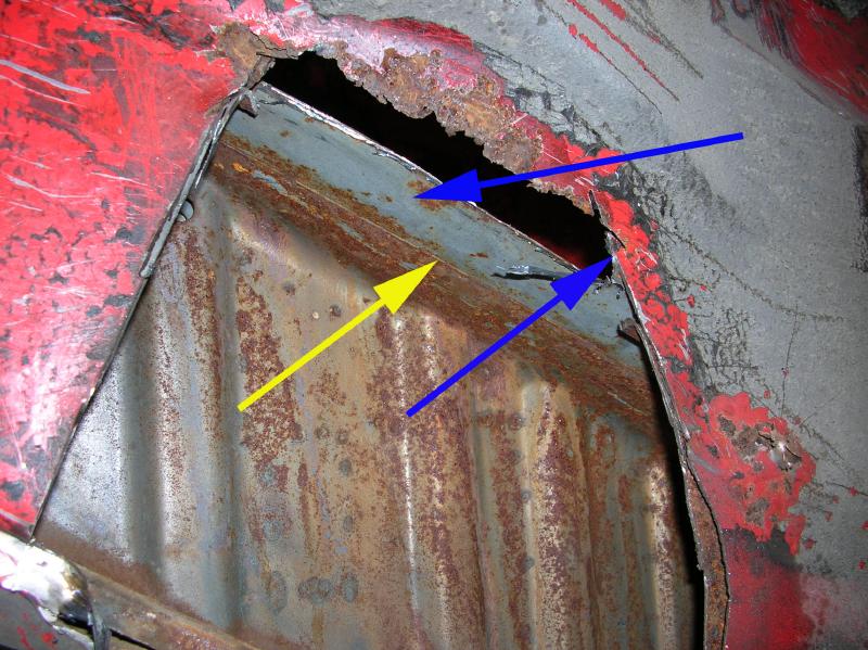
As before, the yellow arrow is pointing to the inner corrugated stamping and the blue arrow is pointing to the smooth outer metal stamping.
Now here is a note that may be of interest; If you were to buy the inner section from Porsche, it would be an assembly made of the two pieces. If you buy the replacement part from Auto Atlanta, it would be one piece and you would see the corrugations within the engine compartment. I'm not bad-ragging the AA part, just pointing out a difference.
The next two photos are of interest, but also are out of sequence.
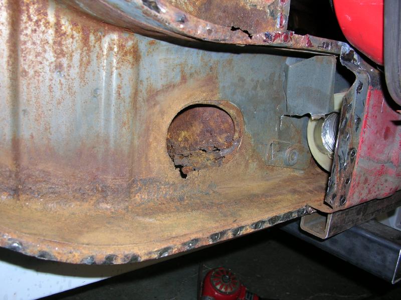
This photo shows the inside of the longitudinal in the area where the "hell hole" normally eats through. (this was taken after removing more of the inner fender panel)
The next one (shot before removing all of the inner fender and air heat tube) is taken looking down the longitudinal.
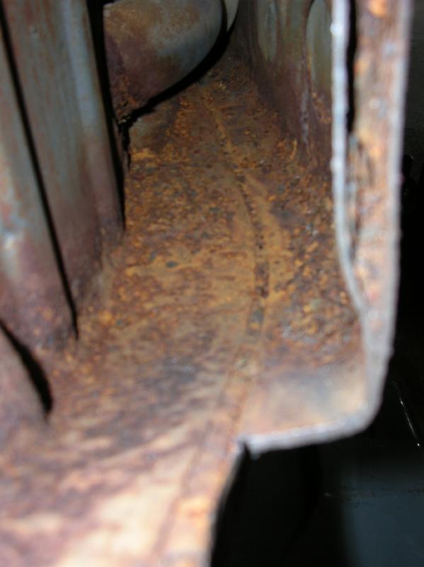
What this all shows to me is that most of the rot was due to water entering through the hole for the hot air tube. I'm converting to a water cooled engine, so I can weld a gusset plate over the hole.
This is not as bad as I was expecting!
The "concept" that I came up with was to replace the outer longitudinal section along with the inner fender panel (which, as I've said, comes as an assembly from AA) and then "skin" the engine compartment side of the longitudinal with three gusset plates (easier to form and install).
In the next two photos, you can see the "hot air" vent hole filler plate I made up. (the welds are not finished!!)
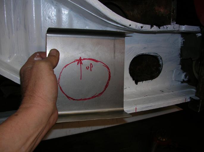
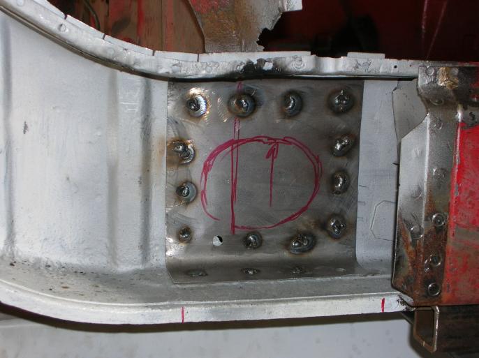
Keep in mind that I can do this due to converting to a water cooled engine. The vent line will not be going back in.
From an engineering standpoint, the holes required for this vent line just seem wrong!
The following photo shows how I treated the inside of the longitudinal with SEM Rust-Seal (think Por15).

The following three photos show the upper gusset plate as I was forming it. (keep in mind that when done, there will be three plates covering the engine compartment surface of the longitudinal, seam welded together) It's made of 18 gauge steel sheet.
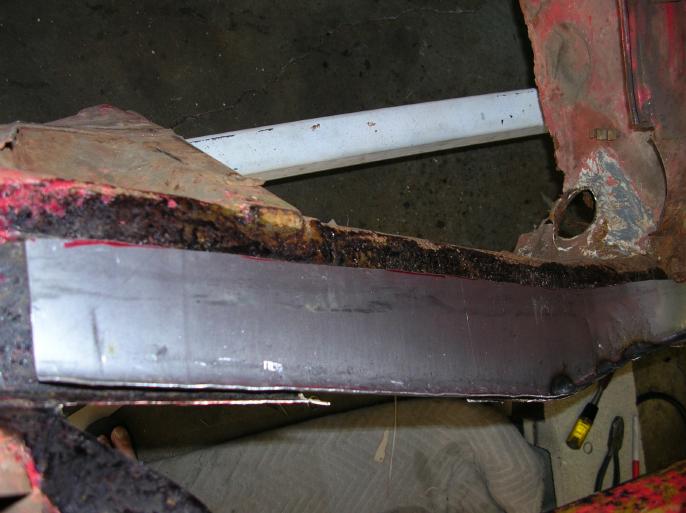
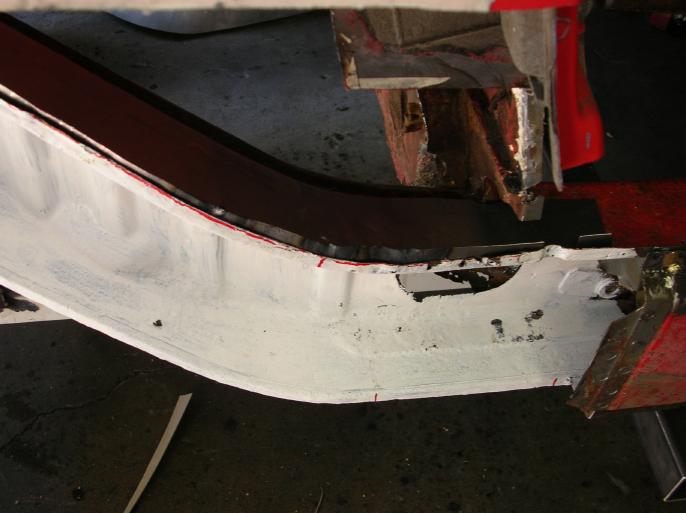
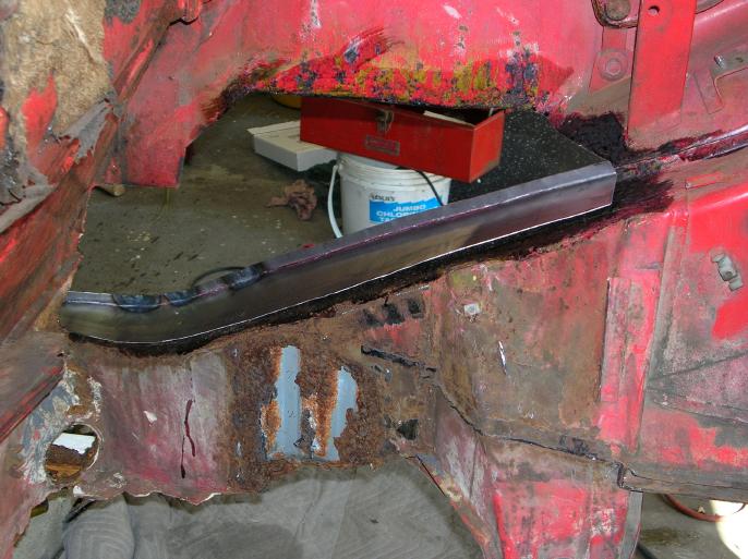
And here is the gusset welded in place;
Here is a treat for those with really good eyes; The plate shown in the photos as welded in place, isn't the same one shown in the earlier photos. All I'm going to say is that not only can you not weld to rust, "you can't weld to "rust converter"!
"Some trimming required";
At this point, I was close to welding in place the panel from Auto Atlanta. The following photos show the panel clamped in place, after trimming and also the "weld plate" I made for the upper edge (it goes on the inside, where you can't see it when finished).
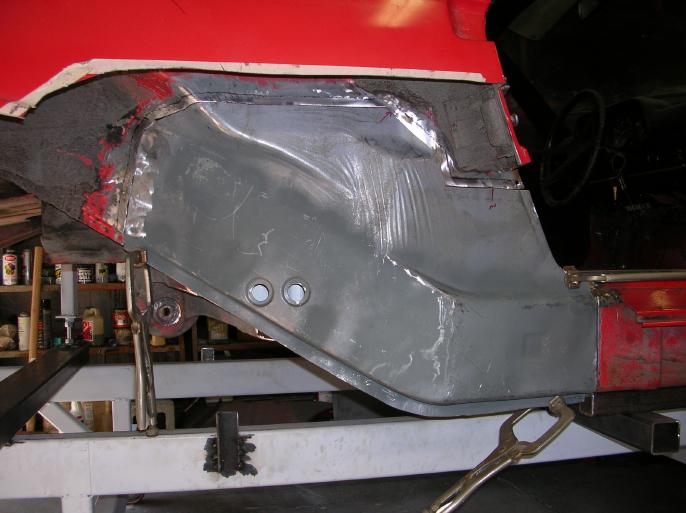
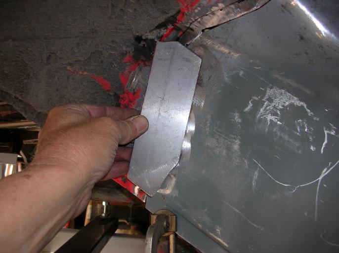
After inspection, and also drilling weld holes, it became apparent that there were issues with the lower edge of the stamping. If you look at the following photo, you can see that the lip is too far down to allow welding to the existing lip.
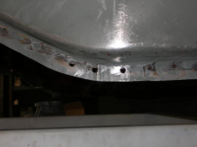
What seems to be happening is that when AA stamped the outer piece, they didn't do as tight a radius to the curves and also not tight against the inner panel.
I could get pissy about it and cry that doesn't fit, but you have to be reasonable! What does bug me is when a manufacturer or supplier posts up an installation write-up, done by their shop, and implies that it fits perfectly.
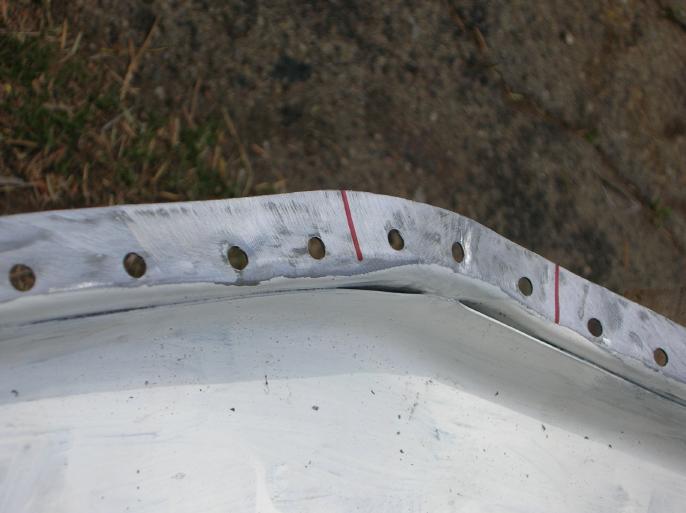
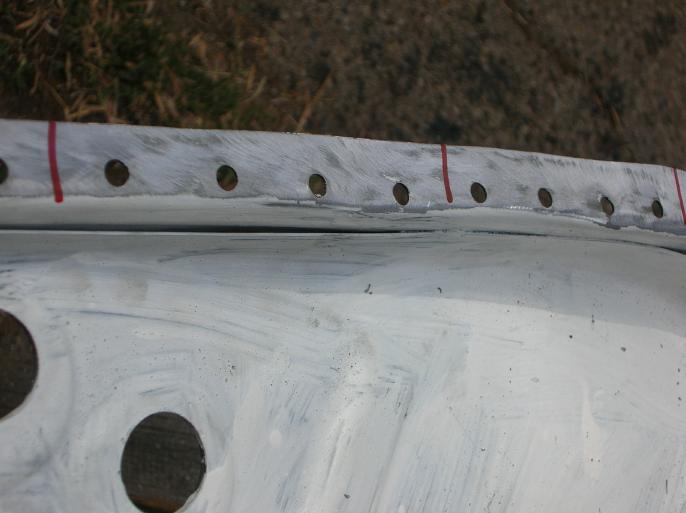
The red lines are where I made cuts in order to re-shape this area.
Re-shaping this area, while off the car, would be difficult due to fact that it's near impossible to clamp it to anything. So, the idea I came up with was to partially weld the assembly in place and re-shape this area while on the car.
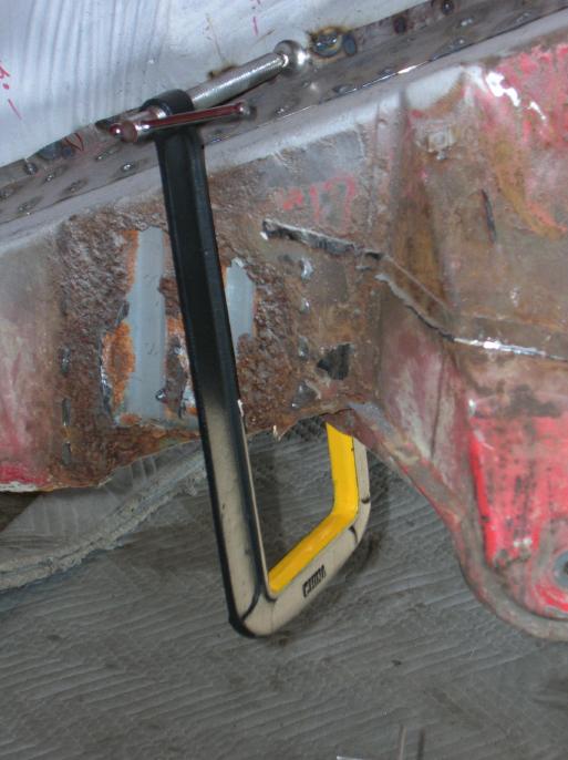
The following two photos show how I used a real deep C-clamp that I bought at Harbor Freight to clamp the upper edge (they are just "mock-up" photos). Once again, the welding isn't finished!
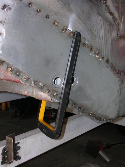
In the next two photos, you can see how I used a large C-clamp and section of round steel (you could use a drill bit) to form up and inward the lower edge.
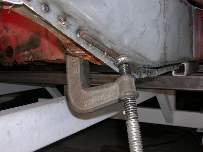
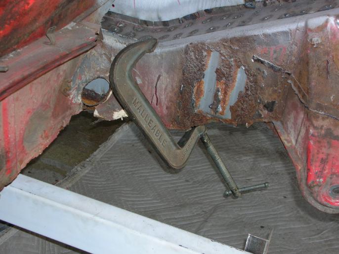
Due to the fact that the clamp is pulling from the corner diagonally across, you need the round stock to put the pressure on the "bend" of the panel. The diameter of the round stock should pretty much match the diameter of the factory bend.
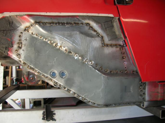
Well, the panel is welded in place. I still have to go in and touch up the welds.
That's it for now.
go to the next "rust diary" page
go to the prior "rust diary" page
return to my "rust diary" entry page
return to my site's entry page
Wes Vann